


Main Window
The Real-Time Designer main window enables you to design a project to be deployed on an agent's computer.
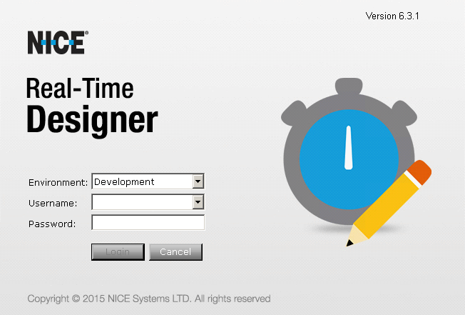
The main window opens automatically when Real-Time Designer is launched and remains open. The content of this window changes according to the module tab that you select.
When you log in to Real-Time Designer, the domain you used to log in to Windows is automatically used. Optionally, you can specify the Active Directory domain to use for your Real-Time Designer login. To do so, enter <domain>\<username>.
|
When logging in to Real-Time Designer, select the environment to which you want to connect. The list of environments is based on the environment set in the Real-Time Designer configuration. To select a specific environment, select it from the Environment drop-down list.
The Stand Alone option enables you to connect in standalone mode, meaning Real-Time Designer does not work with the server. |
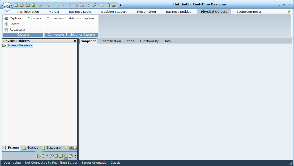
Main Window Components
The following components of the Real-Time Designer main window are common to all modules:
Module Tab Bar: Provides access to each of the Real-Time Designer modules. Click a tab to display the relevant module's window.
Module Tree: A hierarchical tree shows the relevant objects that can be defined in that module. The items that appear in each tree and the available options vary by module.
Quick Access Toolbar: Click the Quick Access icon  on the top left of the screen for quick access to standard generic options, such as New, Open, Save, Save As, Undo, Redo, Clone, Clipboard, and more. The same tools appear in all the modules.
Module Buttons: Provides options for creating and handling the relevant objects that can be defined in the selected module.
Module Work Area: Displays information and enables you to enter information that is relevant to the selected module.
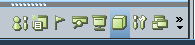
Module Task Bar: You can also access the main window of each module by clicking the corresponding module icon. These icons appear in the left pane, at the bottom of the window.
Quick Access Icon: Provides quick access to general Real-Time Designer functions.
Info Tab: Displays general information about the selected Real-Time Designer object.
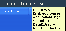
Status Bar: Provides status information about the current logged-in user, the connection to the Real-Time Designer/NICE Perform server and the target orientation of the solution. The default orientation is Classic.

The status bar displays a tooltip when you hold the cursor over the ITI Connect server. The tooltip shows the licenses installed on the NICE Interaction Management/Perform server.
Module Tab Bar
The Module tab bar provides access to the features of the respective Real-Time Designer modules:

|
Module |
Description |
Reference |
| Administration | ||
|
Project |
Enables you to open, validate, generate, and deploy Real-Time Designer projects. |
See Projects. |
|
Business Logic |
Enables you to define the logical entities that determine the behavior of Real-Time Designer according to your business requirements: business rules, workflows, and event handlers. |
See Business Logic. |
|
Decision Support |
Enables you to design decision support, which include KPIs and data collections that can both be used to generate reports. |
See Decision Support. |
|
Presentation |
Enables you to define the items that are displayed on an agent's and a supervisor's screen by Real-Time Designer: callouts, launch in contexts and alerts. |
See Presentations. |
|
Business Entities |
Enables you to design the data structures that represent the business entities of your organization and to instantiate them to represent the actual business entities of your organization. |
See Business Entities. |
|
Physical Objects |
Enables you to design physical objects, which represent the real physical entities (Screen Elements and data elements) of the applications and databases in the environment where Real-Time Designer operates. To design physical objects, you need to use connectors. The available connectors depend on the connectors selected during the Real-Time Designer installation. Depending on the installed connectors, different Screen Elements are captured. Each connector has Physical Object types, identification parameters, and relations that are specific to that connector. Each Physical Object type has specific properties, functions, and events. In some cases, a Screen Element connector can provide functionality that does not exist within Scene Composer connectors. In other cases, Scene Composer can provide functionality that does not exist with any of the Screen Element connectors. |
See Physical Objects. For a list of available screen connectors and extensions, see Connectivity IDD - RTI. |
|
Scene Composer |
Enables you to capture and define scenes and their component objects. In some cases, Scene Composer connectors can supplement the functionality provided by the Screen Element connectors. In other cases, Scene Composer can provide functionality that does not exist with any of the Screen Element connectors. |
See Scene Composer. |
|
Simulated Objects |
Enables you to capture objects using Surface Connectivity when the Real-Time Client and application are installed on different machines and cannot directly connect. Objects are captured by VDI (Virtual Desk Infrastructure). Available only for robotic solutions; cannot be used in attended solutions. |
See Simulated Objects. |
|
|
Displays information about Real-Time Designer. |
|

Info Tab
The Info tab appears in Real-Time Designer for every object that you define. It provides general information about the selected object.
When searching for an item or looking at the Referenced By attribute in the Info tab, Real-Time Designer shows the full object path to the object, including the containing module and the containing project.
To view the Info tab:
| 1. | Select a Real-Time Designer object in the tree. |
| 2. | Select the Info tab in Module work area. |
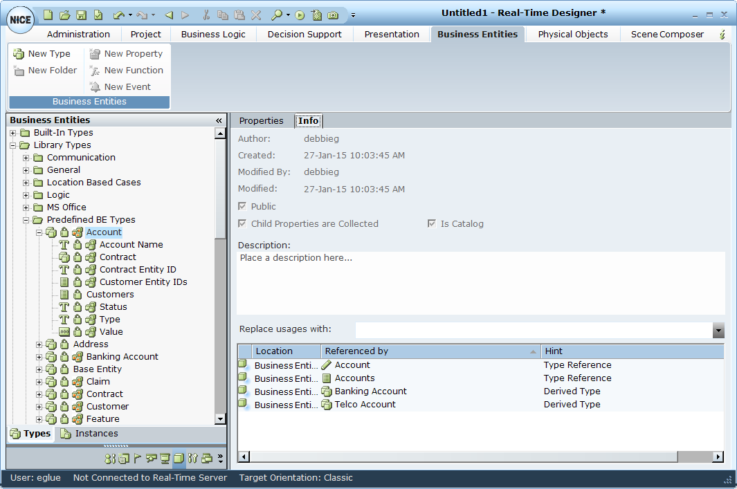
The following object parameters are displayed:
Author: The name of the logged in Real-Time Designer user who created this object.
Created/Modified By/Modified: The date and time when the Real-Time Designer object was created, by whom, and when it was last modified in Real-Time Designer.
Public: A public object creates an interface for other projects, meaning the object can be accessed by another project for which a reference to this project was defined. See References for a description of how to create a reference between projects.
Child Properties are Collected: Marks all the primitive properties of this element as collectable.
Is Catalog:
Description: Enter any textual description of this Real-Time Designer object.
Referenced by: Provides a list of the objects that use or reference this object.
If the Reference By option is disabled, the object is a private object in the Reference project.